One man's struggle to take it easy
Cabin Control System
Wednesday, Dec 17, 2014
The past few months I’ve been working on a control system for the cabin. Initially I wanted an easier way to turn on and off the video motion detection when I arrived and left the cabin instead of having to boot up the laptop. I wanted to be able to switch it on/off it with my phone. Then I wanted to be able to view the snapshots remotely. And monitor the temperature in the cabin…
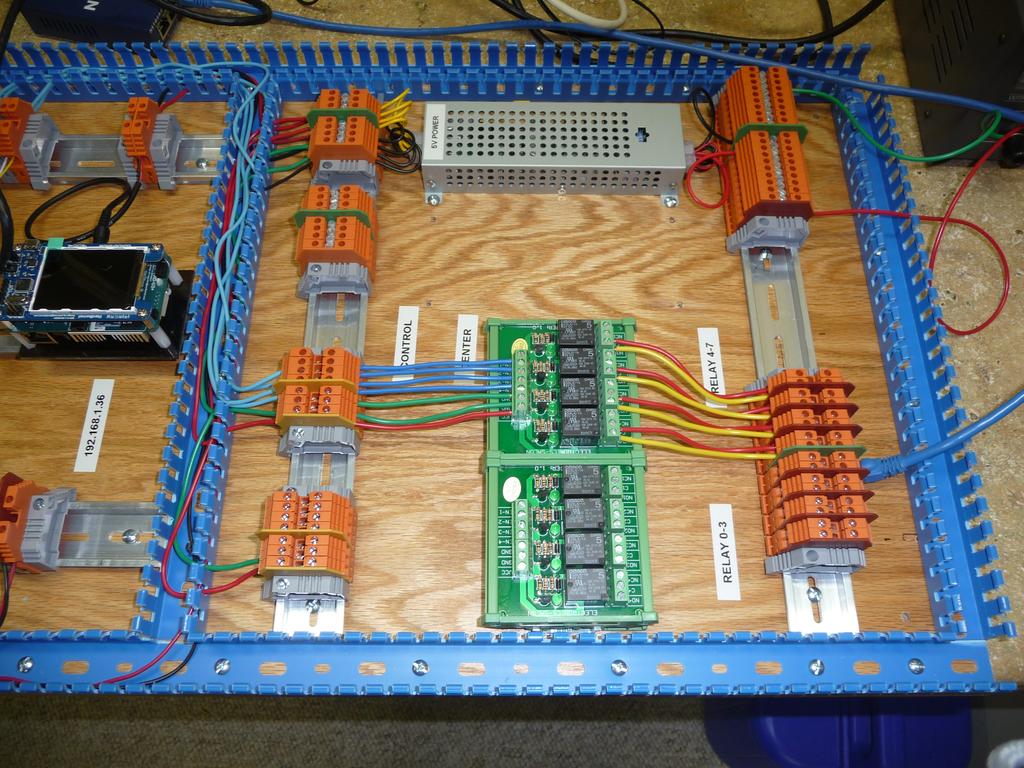
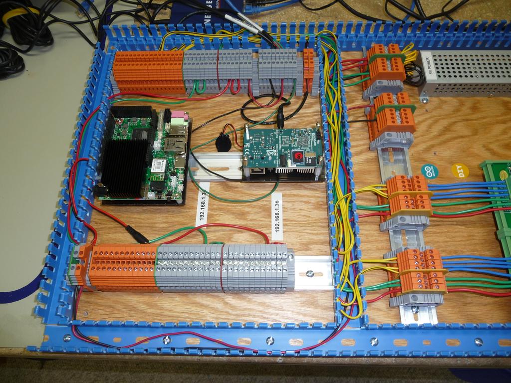
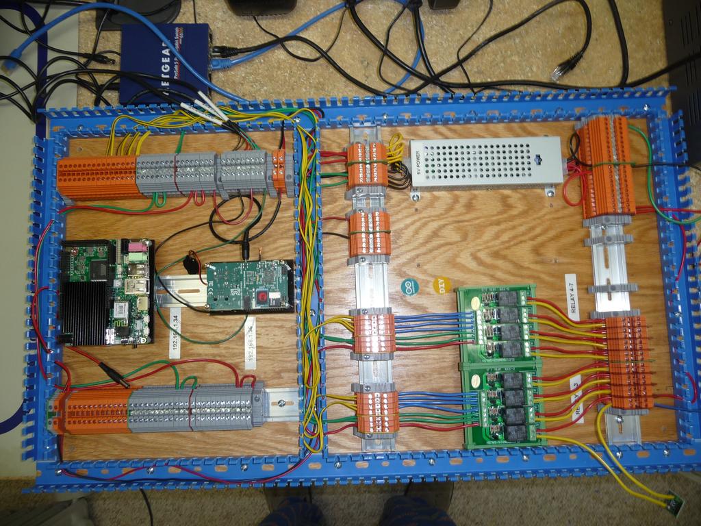
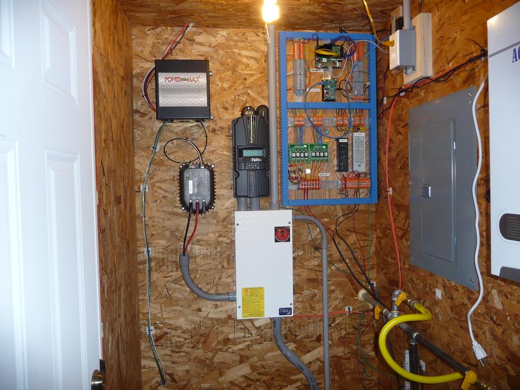
Well, you get the idea. The project as it stands today consists of:
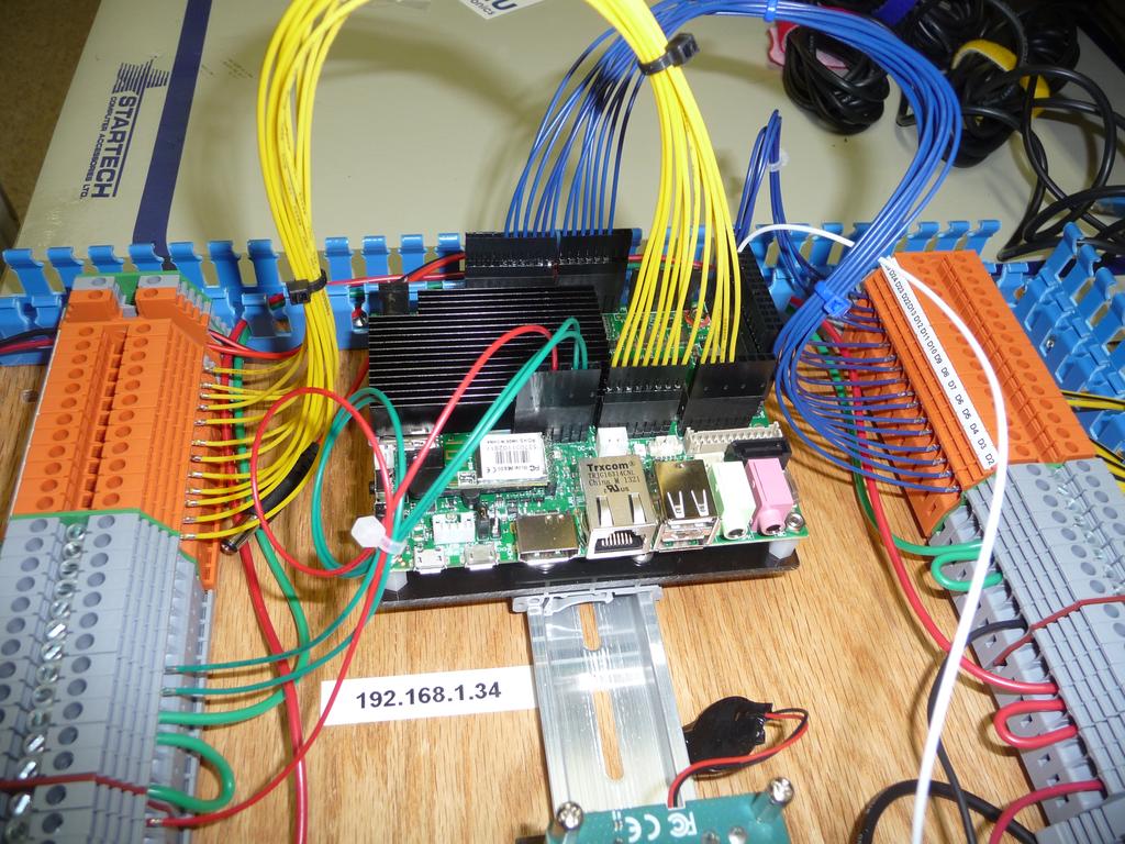
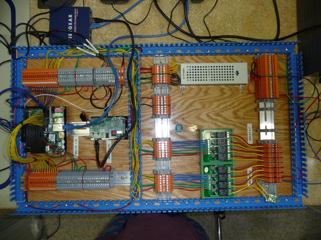
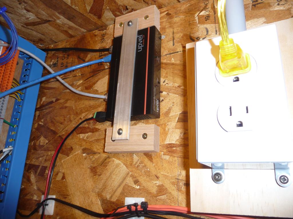
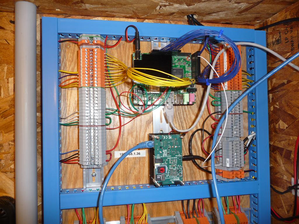
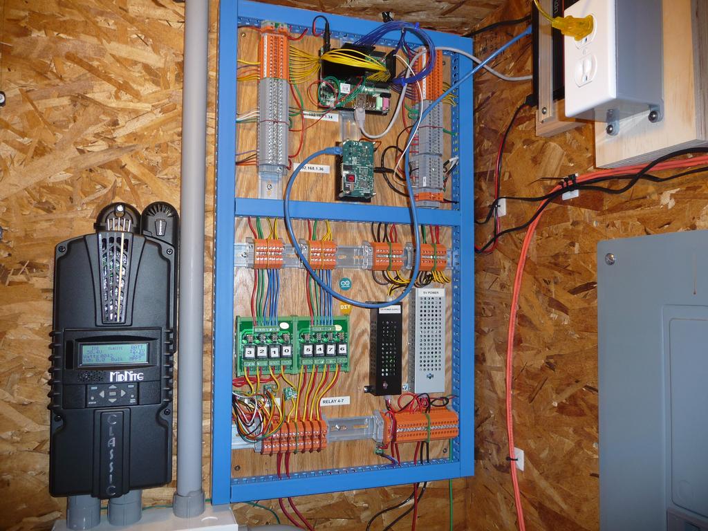
- 2 Control boards, one for the motion detection and to run the local web application (Odroid U3) and one to control all the inputs and outputs (Udoo Quad)
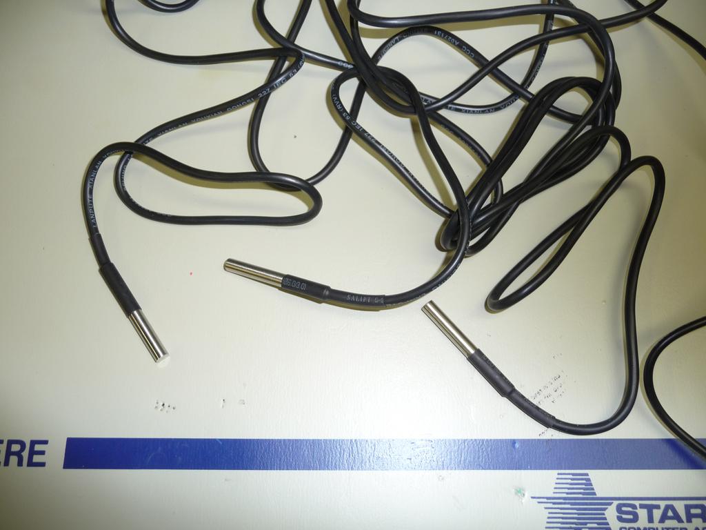
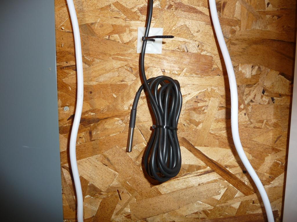
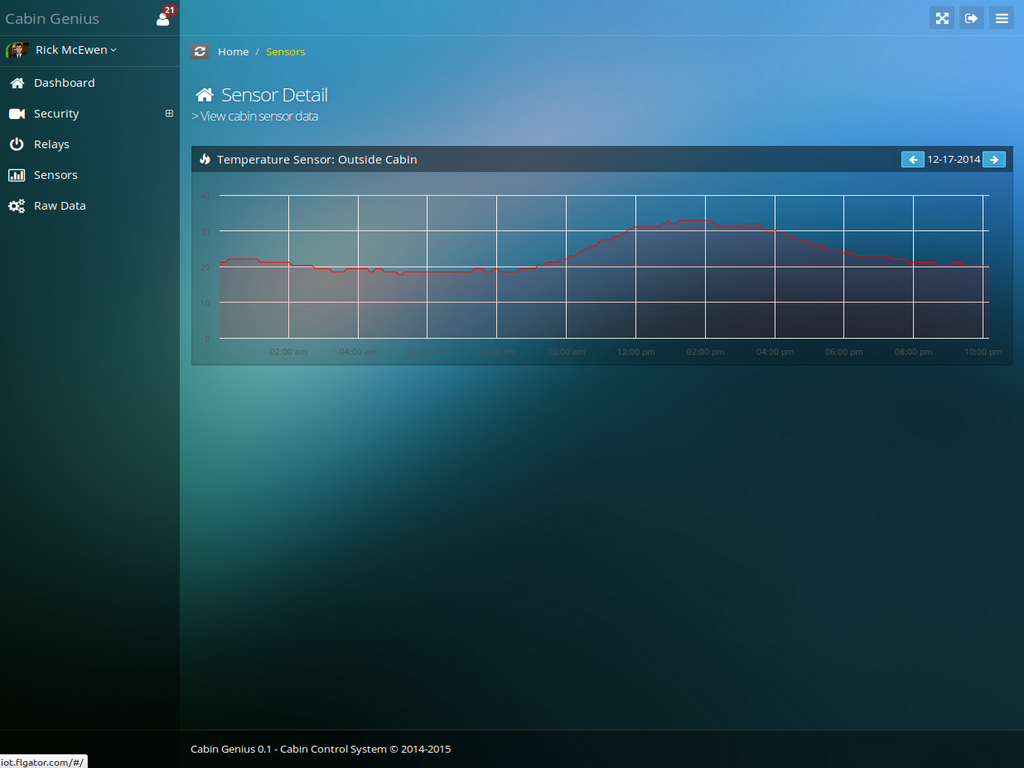
- 3 temperature sensors (inside, outside, utility room)
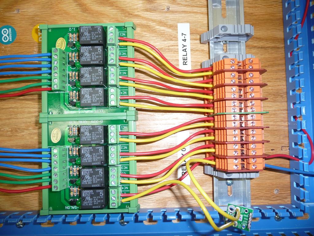
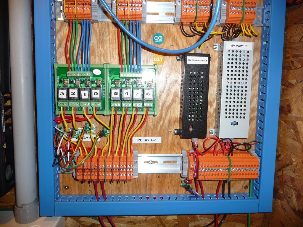
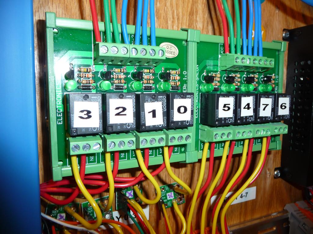
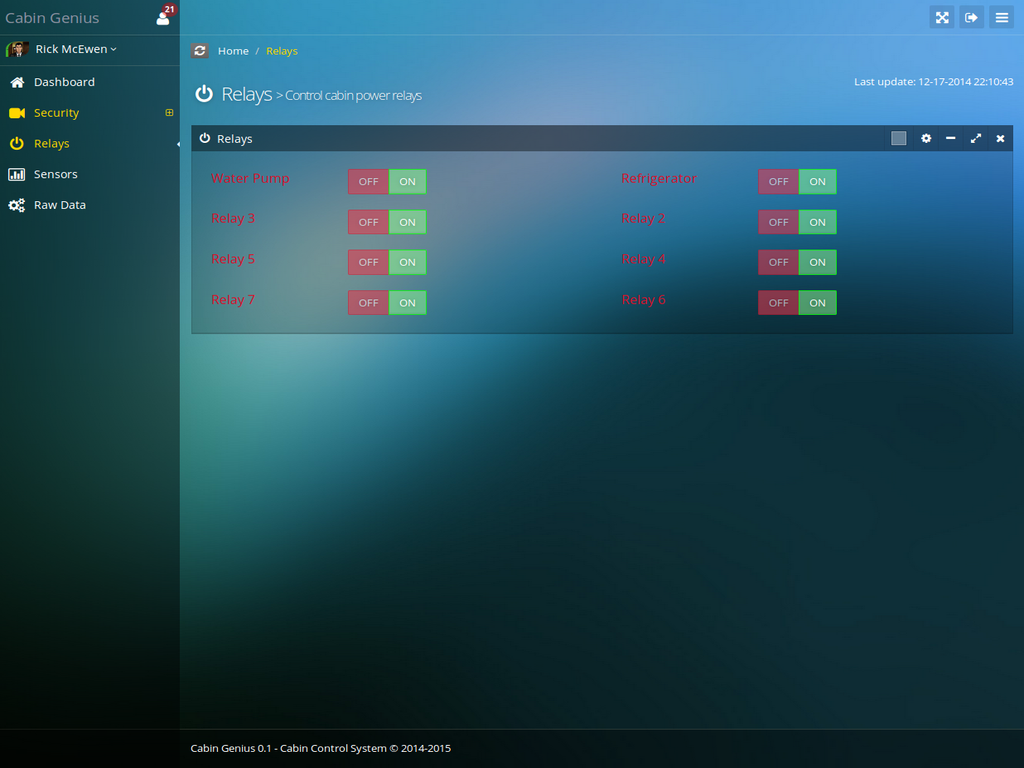
- 8 relays
- 1 voltage sensor
- 5 current sensors
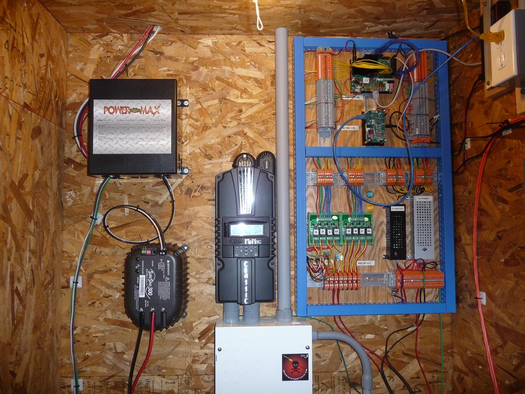
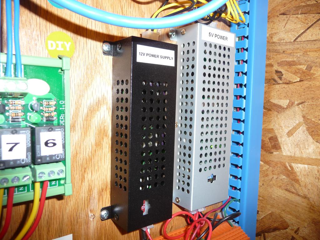
- 2 power supplies (5V and 12V)
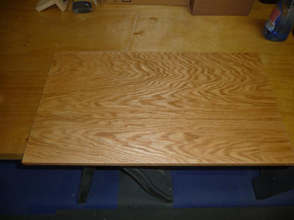
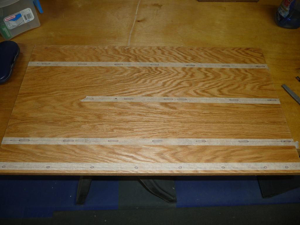
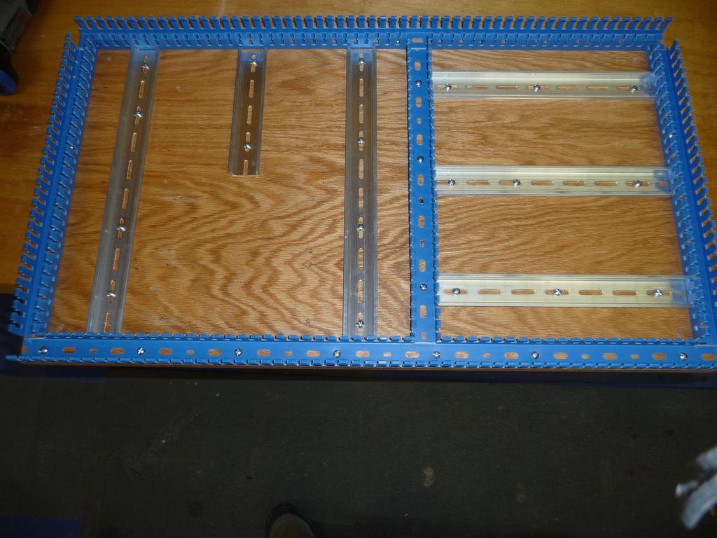
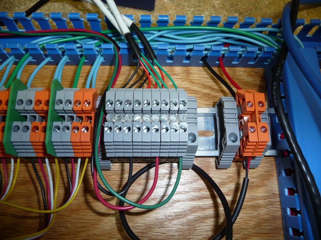
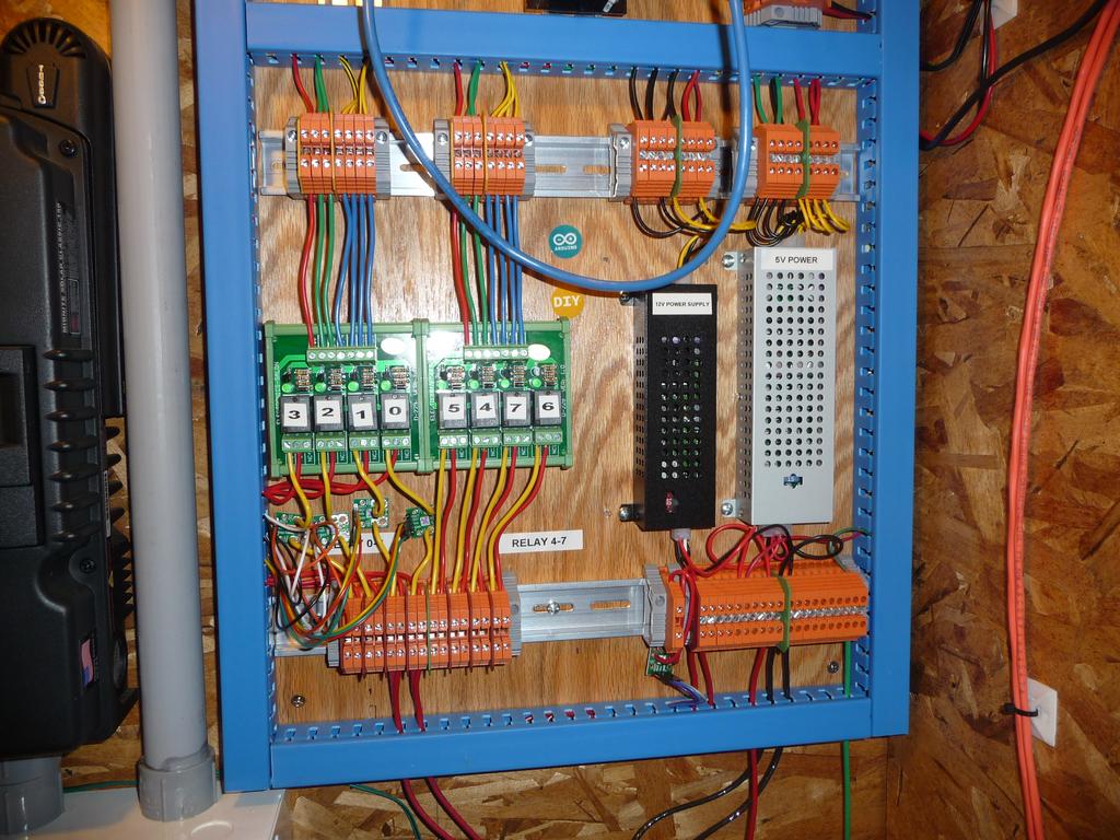
Everything is mounted on din rails with a plywood backing.
The web application operates in two modes, local and remote.
In local mode, the web app runs on the Odroid and communicates directly with the motion capture service, also on the odroid, and a web service on the Udoo to control the inputs/output. The web service on the Udoo talks to the onboard Arduino Due via serial. There are also two services on the odroid which upload the camera snapshots and sensor data to the remote version of the web application (via 3G modem).
The remote web application stores the snapshots and sensor data in a database so has access to time series data. Otherwise it functions the same as the local app other than it uses the MQTT protocol to send commands to the local application so it can control everything remotely.
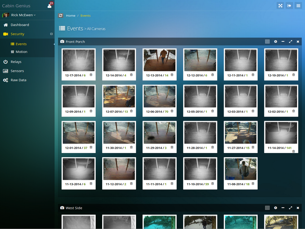
The only feature the local application has that the remote application doesn’t is a live feed from all the security cameras.
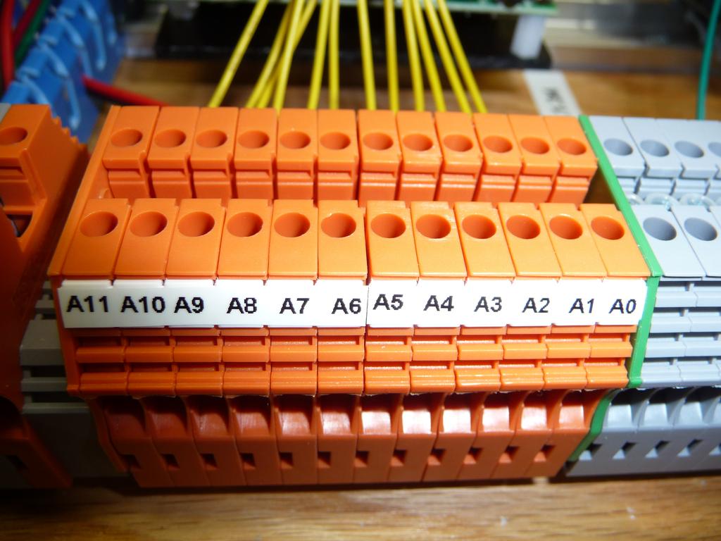
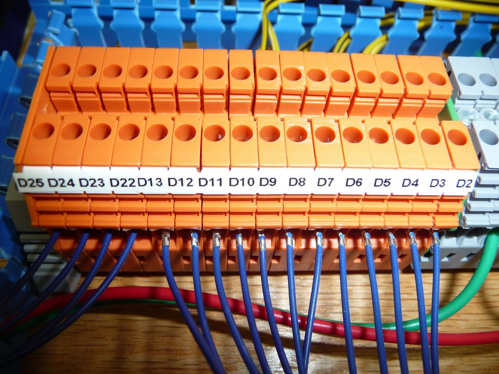
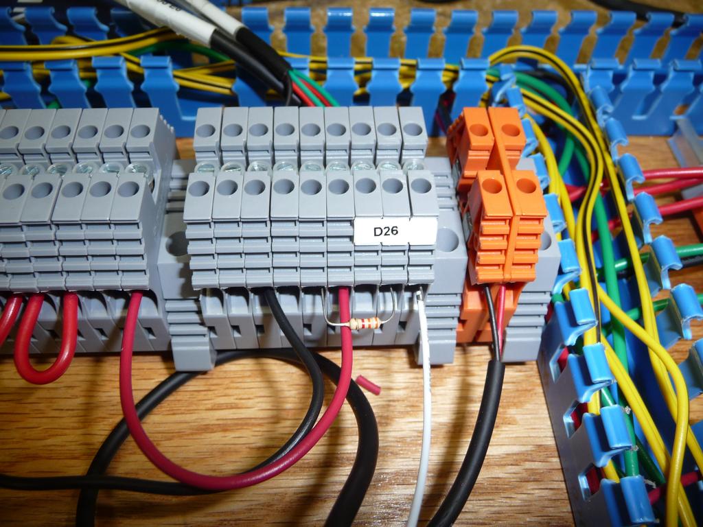
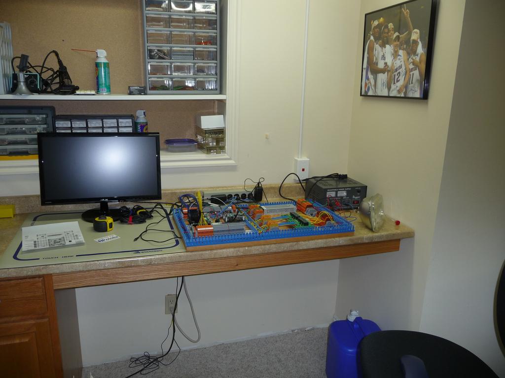
Here are photos of the controller being constructed and installed in the cabin.
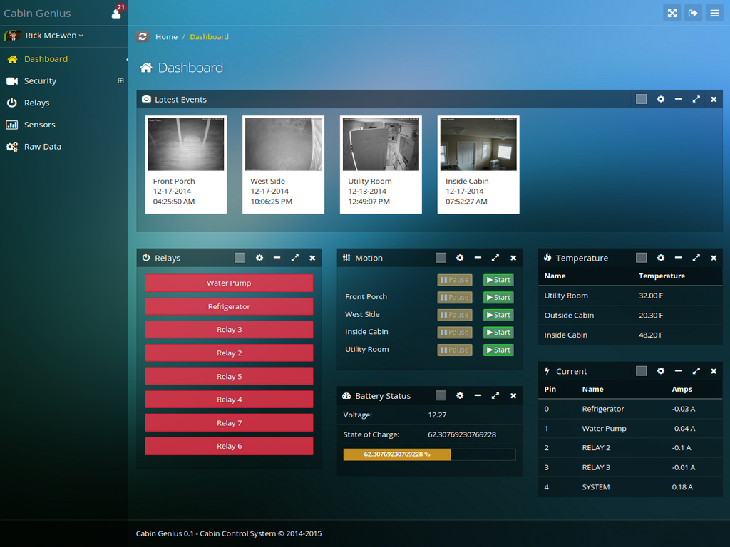
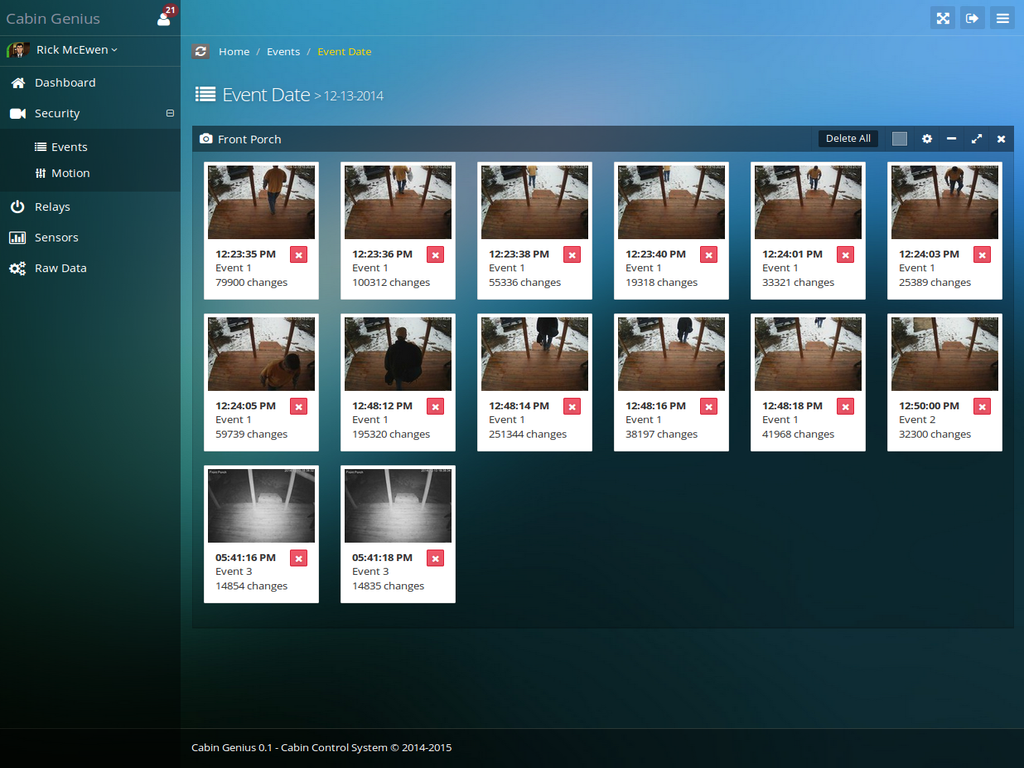
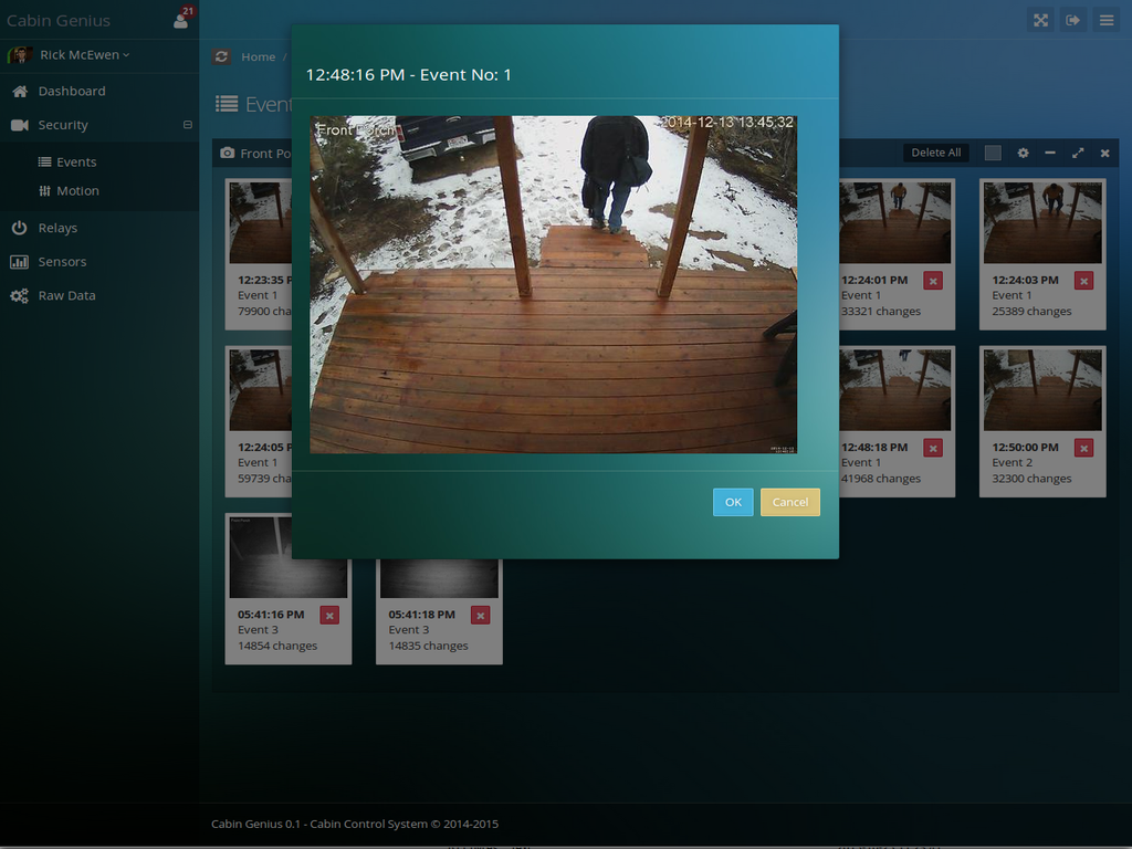
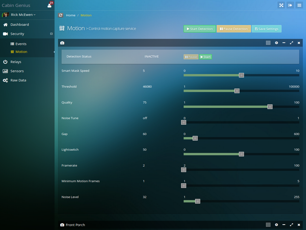
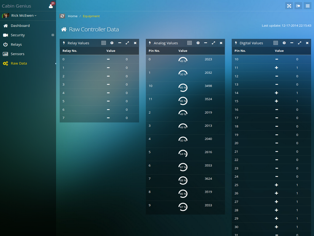
Here are screenshots of the remote web application.


I still don't have every problem worked out and new issues pop up from time to time. I haven't done much work this year so far because I've been busy with other things. I'm planning on using the rest of the summer/fall to mostly do maintenance like re-staining the exterior siding. I'm also going to build a walkway between the new shed, the front porch, and the utility room. That's my top priority right now.
So feel free to ask any questions you have and I'll do my best to answer them.
Glad to hear you're starting your own off-grid place. Building my cabin has been a great experience overall and I'm often astounded that I actually built the thing almost entirely by myself. I'm several years older now and don't believe I could have done it if I started now. I still have some work to do and improvements to make but all the big projects are done I think.