One man's struggle to take it easy
Arduino Wind Speed Data Logger
Monday, May 10, 2010
My long-term plan for providing electricity when I eventually reside on the land involves a combination of solar panels and wind turbine(s). I wanted an accurate measure of what the general wind situation was like at the location in order to determine if wind turbines were feasible and to be able to estimate how much power I would be able to extract from the wind. I decided to place some kind of wind speed data logger at the location to provide this data.
The primary issue was that I currently have no full-time electricity in the mini-cabin so I needed something that would run for weeks or months on battery power, otherwise I would have just used a computer and store bought weather station. I did find a couple of existing battery powered data loggers but they were fairly expensive. In any case, I built my own.
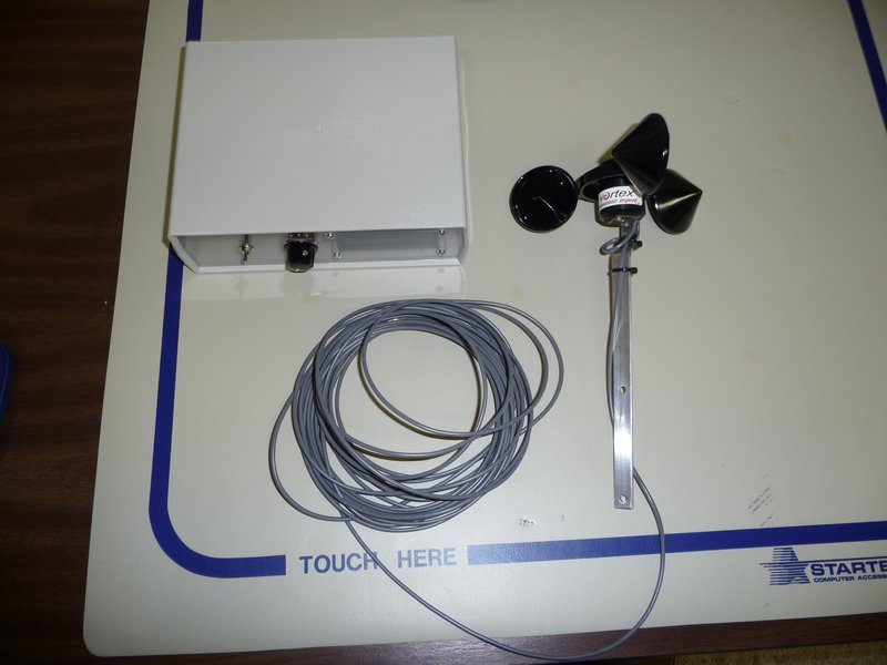
Wind Sensor/Anemometer:
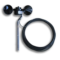
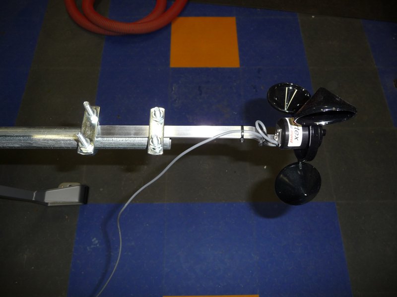
For the actual sensor component, I used an Inspeed Vortex.
This sensor uses a reed switch/magnet to send one pulse along the wire per revolution.
The wind speed is calculated using the formula: 2.5 mph per Hz (1 Hz = 1 pulse/second)
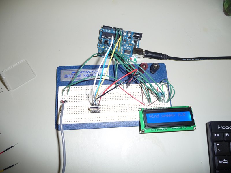
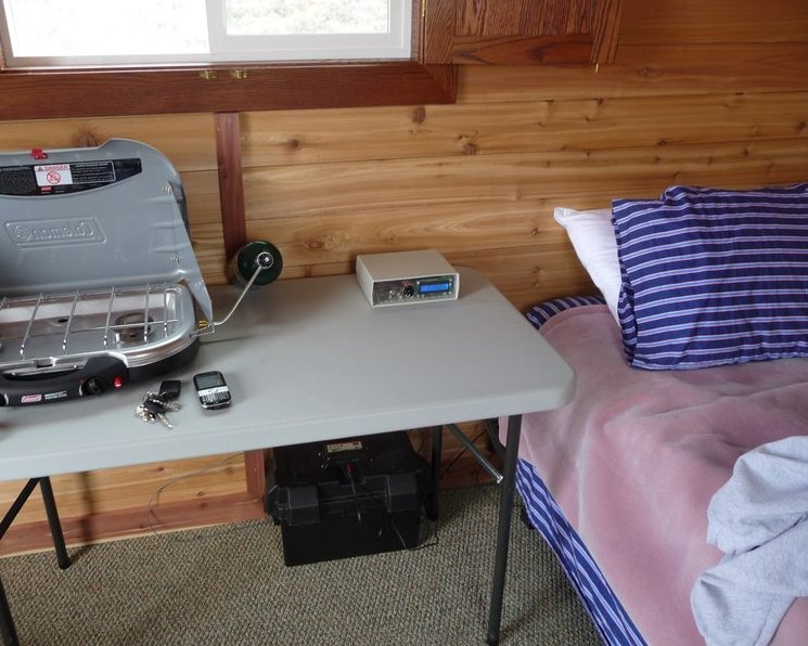
Data Logger:
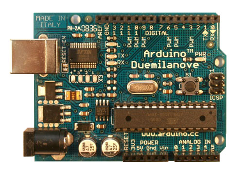
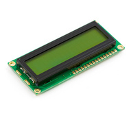
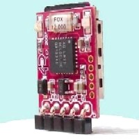
I used an Arduino Duemilanove for the processor, a 16x2 LCD to display output and status messages, and a uDrive from 4D Systems to log to a microSD card.
The Arduino Duemilanove is a microcontroller board based on the ATmega328 (datasheet). It has 14 digital input/output pins, 6 analog inputs, a 16 MHz crystal oscillator, a USB connection, a power jack, an ICSP header, and a reset button. It can be programmed in c using the Arduino IDE via a USB connection to a computer.
The LCD is a standard 16x2 parallel character LCD w/ backlight. I’m using it in 4-bit mode to reduce the required I/O pins.
The uDrive is a microSD card module that supports a serial interface and a FAT16 file system (as well as raw mode). I did experiment using an SD card directly via the Arduino’s SPI interface. It worked fine but none of the available libraries supporting FAT had as complete a feature set as the uDrive or seemed robust enough. The uDrive was simple to connect, simple to program, and was very reliable. The only issue I had was trying to mount it in an enclosure.
The Arduino counts the pulses from the wind sensor via an interrupt and every 10 secs calculates the wind speed and 1) displays the speed on the lcd, and 2) writes the speed to a file on the SD card. It also keeps track of the average wind speed over the previous 30 minutes but just displays it on the lcd.
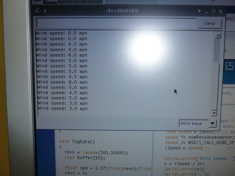
Serial output while testing:
When connected to a PC via the Arduino’s USB/Serial interface, a simple menu can be used to send commands to the data logger, including: Read File Data, Erase File, List Files on Card, Pause Logging, Restart Logging, and Show File Size. The Read File Data command can be used to retrieve the data on the SD card without having to remove the card.
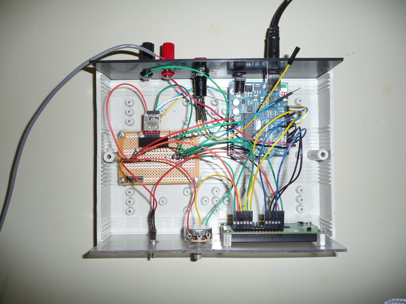
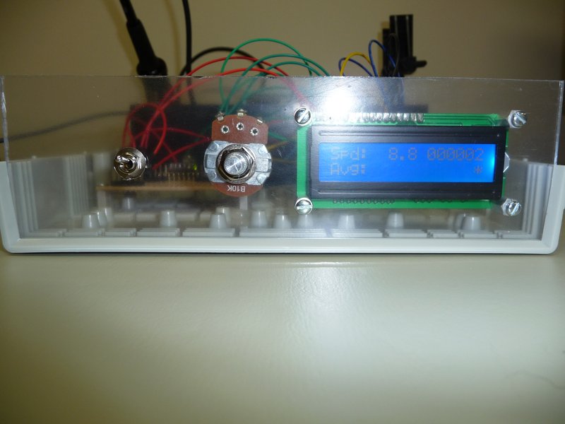
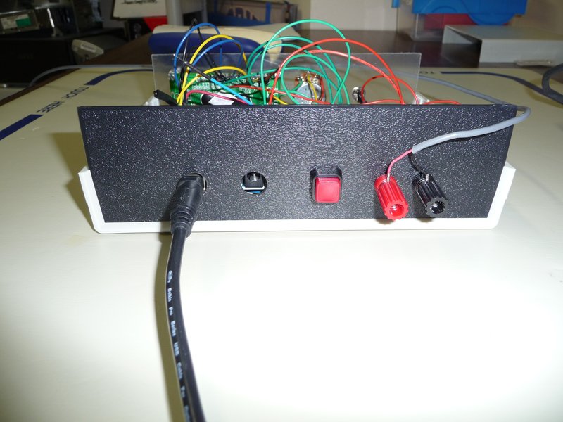
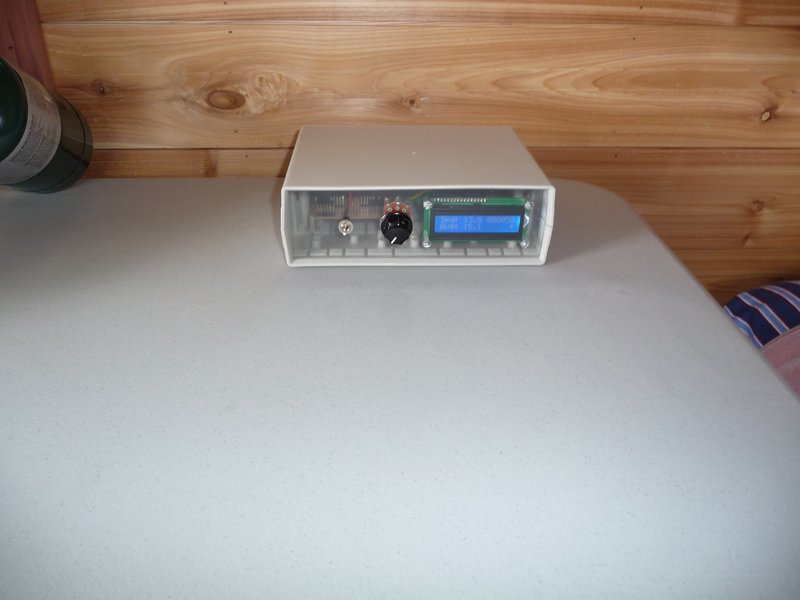
I mounted the components in a project case with a pot for controlling the LCD contrast and a switch to toggle the backlight on the LCD (to save power when not needed).
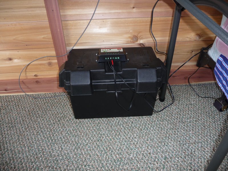
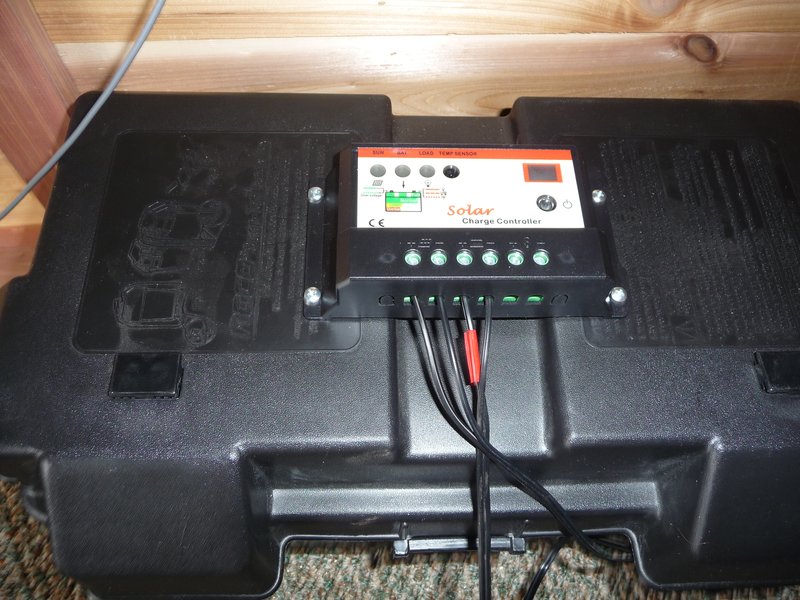
Powering the Data Logger:
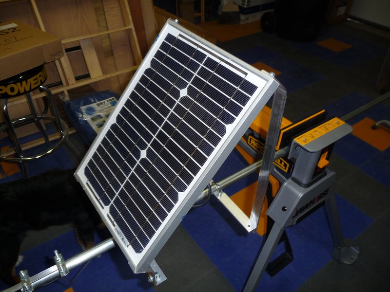
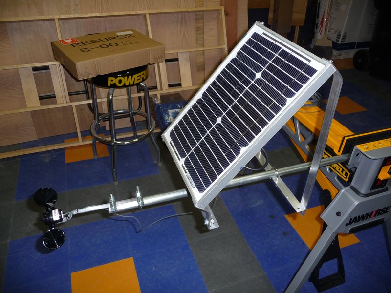
I was already using a deep-cycle battery for power while staying overnight at the mini-cabin which I would charge at home and take it back and forth. The 12V battery would power the data logger directly so I bought a 10W solar panel and a charge controller to keep the battery charged continuously. The small draw of the data logger probably wouldn’t drain the battery for months but since I use the battery for laptop, light, etc., when staying at the mini-cabin, I needed to be able to replenish the charge to ensure the data logger runs continuously.
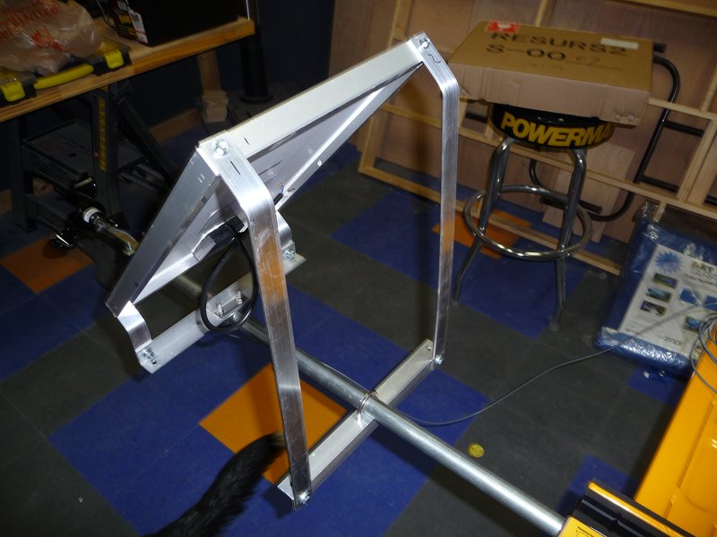
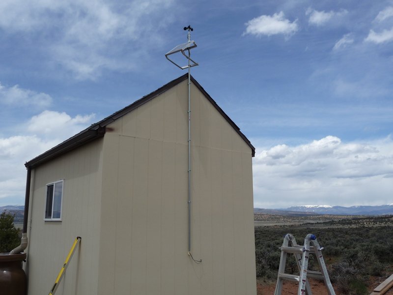
I made a mounting bracket for the solar panel from aluminum angle and flat and mounted it to a 10’ piece of 3/4” emt. I also mounted the wind sensor to the emt using u-bolts.
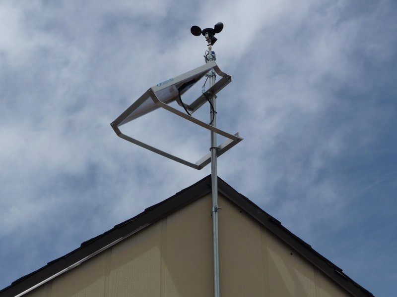
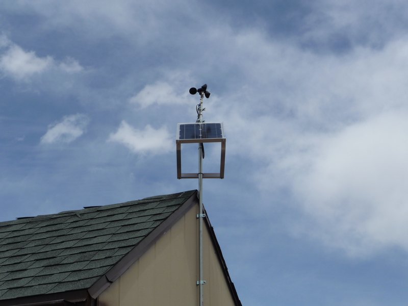
I mounted the panel and sensor pole to the side of the mini-cabin using five emt standoffs. The wires run down the center of the emt and through the side of the cab where they run to the charge controller and data logger.
Results:
The data logger powered up and started logging data perfectly. The wind speed varied from 6mph to 36mph while I was on-site. I’ll be back next weekend to check the data for the week.
Notes:
- The sketches (source code files) for the data logger are available here.
- My rough costs for the data logger are as follows:
Arduino
$29
LCD
$13
uDrive
$29
Wind Sensor
$55
Misc. Components
$20
Solar Panel
$60
Charge Controller
$55
EMT, Wire, etc
$10
- If I had to do it all over again, I might use one of the Arduino data logging shields that have emerged since I started this project such as the Adafruit Data logging shield or an Arduino with a built in RTC and SD card socket such as the Seeeduino Stalker.
I just want to ask you whether you are the person that implemented the sketch to read wireless data from an Oregon Scientific Weather station. The solution was mentioned in the Arduino Forum. I am very interested.
Danks in Advance
Regards from Switzerland
Thomas
I'm not that person, but he's a friend of mine. His name is Brian and his email is brian@lostbyte.com. His site with the details has been down for a while due to server problems but I spoke to him and he said he'd try to get it back up in a day or two. Feel free to email him directly for more info.
Rick
thanks for you quick response. I will contact him directly.
Thomas
I am working on a similar project looking for similar site solar and wind energy potential. I am using an NRG #40C anemometer (produces an AC sine wave proportional to wind speed) and am having trouble with the Arduino counting noise. Thank you for this information, I hope your method will be what I am looking for.
Walter
I am looking into connecting an NRG #40 to an Arduino and found your blog very interesting. Could you let me know how you interfaced the anemometer to the Arduino. Do you have a circuit diagram and component list that I could use?
Thanks in Advance
Lee
The model I used basically just closes a switch once per revolution so the wiring is simple. There are only two wires. One wire is connected to ground and the second wire is connected to a digital IO pin that supports interrupts. So then I just set an interrupt handler to fire when the IO pin is FALLING, which happens when the switch closes.
It looks like the device you're considering is more complicated than mine and sends a sine wave signal. I don't think you could measure that with an arduino since the peak voltage of the sine wave is only 80mv. It looks like some people have hacked that anemometer to use a hall effect sensor instead which would make it operate like mine does.
http://forums.adafruit.com/viewtopic.php?f=25&...
Others have used some type of frequency to voltage converter to use it with an arduino but that's beyond my skill level.
http://forum.allaboutcircuits.com/threads/reading...